If you just finished building your new house, chances are you designed your own home network to suit your needs and every inch of your home is covered in wireless/wired internet access.
But what about the rest of us? Moving or living in an older house? Wireless and Powerline adapters just don’t do it for you?
Simple! Run your own Ethernet wires.
Although wireless is simpler for a lot of people, due to poor signal quality, and concerns about wireless security, you may want to use a wired solution for home networking. Having a wired Ethernet network at home allows you to have a private, high-speed network for internet access.
In this post we will go over how to make and run your own Cat5e / Cat6 Ethernet wiring in your home.
Step 1: Planning
There are certain design considerations that need to be addressed based on your needs.
––– Which room are you planning to wire? You will need to make sure you can pass Ethernet cable from your router/switch location to the room you wish to wire. This can be done using the existing wiring installation in your home or you will need to drill holes through walls.
––– How many ports will you need in each location? Depending on your needs you might want to wire more than one port. Each additional port you wire will need its own separate Ethernet line. So you need to consider each wire’s diameter when using existing wiring installation tubes as many older houses don’t account for 2 or maximum 3 wires to be run in each tube. Also you need to make sure your router or switch has available empty ports to accommodate the new lines.
––– What network speed? This mainly depends on the rest of your network gear. A lot of router’s in the market are still capped at 100Mbps speeds. While you might think that is enough since your internet connection may still be less than that you need to consider that this speed will also affect any communication between devices in your home network. For example a file transfer within your home network will be considerably slower even if your NAS and computer support Gigabit network. Cat6, while a bit more expensive, is highly recommended for wiring as it is certified to handle Gigabit Ethernet, is better suited for wiring due to better interference resistance and is more future proof.
Next: you will need some things.
Step 2: Required Tools and Materials
Your tools and materials (and costs) can vary a lot based on your needs. At a minimum you will need the following:
- Cat6 UTP solid copper wire
- Wire stripping tool
- Ethernet crimping tool
- Punch down tool
- RJ45 jacks and RJ45 wall plates
- Network tester (Optional)
- Fish Tape (Optional)
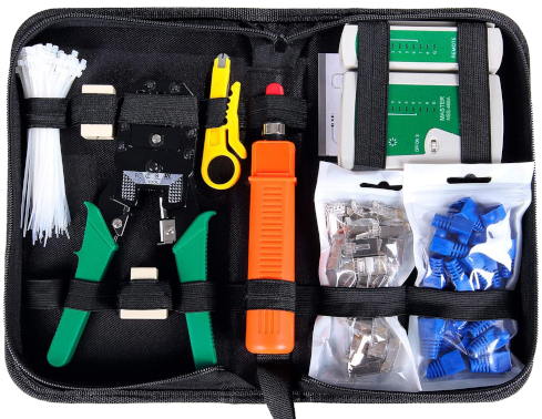
I recommend getting one of these network kits which should contain all the tools you will need (except the Cat6 wire and wall plates) and is actually cheaper than buying all the tools separately.
Next: we can run cables.
Step 3: Measure and Run the Cables
If you are not a professional you most likely don’t have the necessary tools to run wiring through existing wiring conduits.
For this you have two options:
a) Use an existing wire you no longer need, such as an old telephone line or antenna wire, and use it as a guide to run your Ethernet cable. You can tie the old wire in the tube with the Cat6 cable and pull from the other side thus feeding the cable in the conduit while the old wire is extracted.
b) Purchase a tool called “Fish Tape” to guide the wire through. You could hire a professional but that will defeat the purpose of this whole process as the professional will cost a lot of money for something that you can easily do on your own over a weekend.
All that remains is measure the length of the cable needed and cut it to size from the spool. You should leave some slack to the cable for any bends/turns in the way and also, if you are a beginner, for any mistakes you might make in the wiring later that will need to be cut.
Most importantly follow the golden rule of “measure twice cut one!”.
Next up: making connections.
Step 4: Connect the Wires to the Wall Plates
Now that the cables are sorted the only thing that remains is connecting the wires to the wall plates, patch panel or RJ45 jacks to complete the process.
Whether you are terminating the cable to an Ethernet Wall plate, Patch Panel or RJ45 jack for connecting directly to a switch or other device, the process is quite similar.
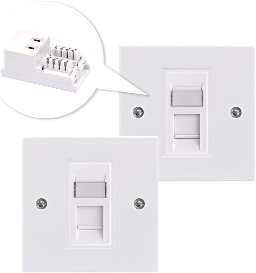
In this example we will be terminating the cables in a wall plate. Each wall plate comes in two parts. A smaller mounting bracket where the cables will be installed and the actual wall plate that will be screwed in your wall socket.
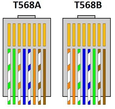
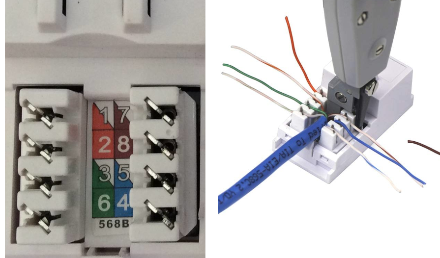
Most Patch Panels and Ethernet Wall Plates have diagrams with wire color instructions for the common T568A and T568B wiring standards.
We will be using the T568B color coded standard as it’s the most widely used and will give you the most chances of compatibility with other devices in your home network.
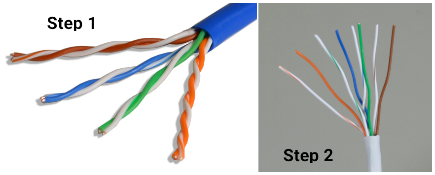
First thing you need to do is strip the outer shell of the Ethernet cable. Be careful not to damage the small internal cables. Once you have the outer shell removed go ahead and untwist each pair of the colored cables so you have each colored cable separate.
Once you have the wires prepared just insert them in the correct slots based on the color coding diagram on your wall plate / patch panel as explained above and make sure they are firmly in place.
Then use the Punch Down Tool to push the cable in the slot and cut any excess wire hanging from the side.
Repeat the process for each side of the cable. Screw the wall plate back into the socket and you are all good to go.
Now we can make sure things work!
Step 6: Test the Connections
Before you start connecting most of the network components, you want to test all of the connections to be sure things are working.
You can of course connect your router and computer to your newly installed wall plugs and test the internet connection. However if you are unlucky and not managed to make it work on your first try then you have no way of knowing what went wrong.

This is where a network tester comes in handy.
Just plug one end of the cable into the transmit jack. The transmit jack on the tester may be labeled “TX” and plug the other end of the cable into the receiver jack. The receiver jack may be labeled “RX” on the device.
Tip: If you are testing a wall plug make sure to use known good Ethernet cables on either side. Plug a known good cable into the wall plate and connect to the transmitter and plug a known good cable into the wall plate in the other room and connect to the receiver. This helps avoid any errors you may have that are due to faulty cables and not due to your wall plug wiring.
Check the lights on the tester. Most testers will have 2 sets of 8 LED lights that correspond to the 8 pins on the transmitting and receiving end of the Ethernet cable. There will also be a G light for the ground. It will test each pin one at a time. If all 8 pins light up on both ends, the cable is good.
If any of the lights do not light up on either end or if the lights on either end flash out of order, this indicates that you may have an issue with your connections. Out of order lights most probably indicate that you inserted the wrong color coded cable in the wrong slot in your wall plug. If the light does not light up at all this probably means that the wire was not punched down correctly and does not make adequate connection to the slot.
Both issues can be easily fixed using the hook tool on your punch down tool to remove the affected cable/cables and repeat the connection process as in Step 5 above.
Note: Some Ethernet cables are sold rated for 100Mbps only. This means that when tested lights 4 and 5, corresponding to the blue and blue/white wires may not light up. A connection will still be established and the cable will work but it will be capped at 100Mbps speeds. So when testing your connections make sure you are using a cable rated for Gigabit speeds whereas all 8 wires are required and all lights should light up when using a network tester.
EXTRA
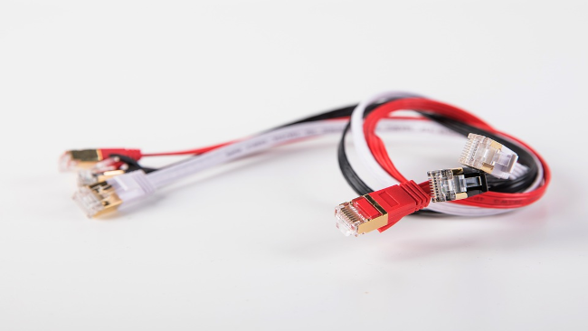
You can follow many of the steps above to make your own ethernet cables as well. this comes in handy when you need a custom length cable to keep everything tidy.
You just need to insert the straightened colored wires into an RJ45 jack and clump down the wire using an Ethernet crimping tool.
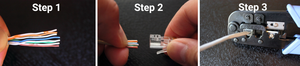
You can refer to the color diagram below on how the wires should be inserted into the RJ45 jack. It will be kind of tricky at first but it will get easier the more cables you make.

As with the color coding for wall plugs and patch panels explained above make sure to use the most common T568B color wiring standard.
That’s all you need to make your own wires and save money installing Ethernet cables in your home.